
Choose which optional cookies you allow. Essential cookies support security, sign-in, your cart and requested features. Cookie consent is separate from SMS consent.

Essential

Required to run the site and remember your privacy choices.

Always active

Applying changes refreshes this page so every tracking tool uses your choice.

Read our Privacy Policy
Skip to content
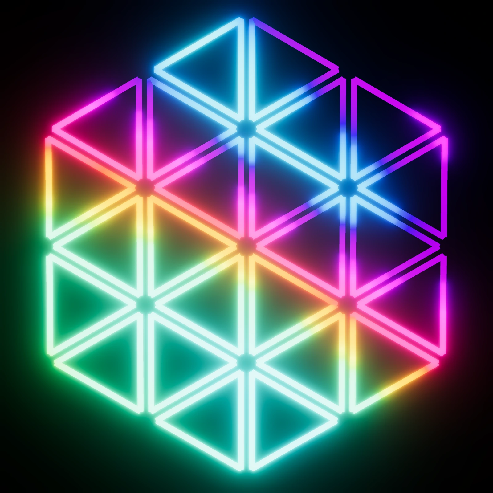
Sacred Geometry triangular light modules arranged in a hexagonal pattern

Sacred Geometry

$10,608.52 · Before shipping and tax

Configure your Sacred Geometry kit

about 39.4 in · 3.28 feetMeters, from 0.5 to 2
1–4 ringsComplete rings of triangular fixtures
about 0.16 ftMeters of clear space between fixtures, from 0.02 to 0.3

Clear space between neighboring triangular fixtures.

24 triangles · 72 lights · 72 m total · 3 nodes

Shipping $0.00 · ground, large boxes, US only

Questions? Call 516-376-2309.

Lights, control system, data leads and nodes included. Tax is calculated at checkout. Lead time is confirmed with your order.

Equilateral light triangles arranged in a hexagonal pattern.

Photos & renders
Sacred Geometry triangular light modules arranged in a hexagonal pattern

Pattern render

What’s included in your Sacred Geometry kit

See how it fits in your space

Sacred Geometry: all 72 lights in their selected arrangementRoom view. 18 feet wide, 20 feet long and 10 feet high. Light lengths and orientations match the controls above. 2 gray 3D scale figures stand on the floor, each 1.75 metres (5 feet 9 inches) tall.Standing scale figure: 1.75 m (5 ft 9 in) tallStanding scale figure: 1.75 m (5 ft 9 in) tallT001-B1: 1 mT001-B2: 1 mT001-B3: 1 mT002-B1: 1 mT002-B2: 1 mT002-B3: 1 mT003-B1: 1 mT003-B2: 1 mT003-B3: 1 mT004-B1: 1 mT004-B2: 1 mT004-B3: 1 mT005-B1: 1 mT005-B2: 1 mT005-B3: 1 mT006-B1: 1 mT006-B2: 1 mT006-B3: 1 mT007-B1: 1 mT007-B2: 1 mT007-B3: 1 mT008-B1: 1 mT008-B2: 1 mT008-B3: 1 mT009-B1: 1 mT009-B2: 1 mT009-B3: 1 mT010-B1: 1 mT010-B2: 1 mT010-B3: 1 mT011-B1: 1 mT011-B2: 1 mT011-B3: 1 mT012-B1: 1 mT012-B2: 1 mT012-B3: 1 mT013-B1: 1 mT013-B2: 1 mT013-B3: 1 mT014-B1: 1 mT014-B2: 1 mT014-B3: 1 mT015-B1: 1 mT015-B2: 1 mT015-B3: 1 mT016-B1: 1 mT016-B2: 1 mT016-B3: 1 mT017-B1: 1 mT017-B2: 1 mT017-B3: 1 mT018-B1: 1 mT018-B2: 1 mT018-B3: 1 mT019-B1: 1 mT019-B2: 1 mT019-B3: 1 mT020-B1: 1 mT020-B2: 1 mT020-B3: 1 mT021-B1: 1 mT021-B2: 1 mT021-B3: 1 mT022-B1: 1 mT022-B2: 1 mT022-B3: 1 mT023-B1: 1 mT023-B2: 1 mT023-B3: 1 mT024-B1: 1 mT024-B2: 1 mT024-B3: 1 m
18 ft wide20 ft long10 ft high

Scale figures: 1.75 m (5 ft 9 in) tall

about 0.16 ftMeters of clear space between fixtures, from 0.02 to 0.3

  • 72×1 m lights
  • 1×Computer & monitor

  • 1×Keyboard & mouse

  • 1×Router

  • 3×Controller & power node

  • 1×Cabling set

  • 1×Mounting hardware set

At a glance

Install difficulty
Moderate
EasierMore involved

Mount, connect and test.

Install time
Layout dependent
Less setupMore setup

Relative to kit size. Hours confirmed with your order.

Lead time
Build and delivery dates confirmed in your quote.
Warranty
Written warranty terms provided with your quote.
Tools
Measuring tape, level, drill and suitable access equipment.
Power
We’ll confirm the supply and circuit requirements.
Shipping & returns
Ground shipping in the US. Review return terms before ordering.
Setup support
Call or text us during setup.

Use the mounting hardware specified for your surface. Have a qualified electrician assess any new circuits or changes to building wiring.

Wiring blueprint

Cat 6 networkPowerFixture feedJST links
Full sacred-geometry lighting connection blueprint72 lights, 24 fixture feeds, 3 controllers and 3 power/drivers in 3 groups. Connection routing is schematic, without vendor-specific pin assignments.F01: C01 to T001F02: C01 to T002F03: C01 to T003F04: C01 to T004F05: C01 to T005F06: C01 to T006F07: C01 to T007F08: C01 to T008F09: C02 to T009F10: C02 to T010F11: C02 to T011F12: C02 to T012F13: C02 to T013F14: C02 to T014F15: C02 to T015F16: C02 to T016F17: C03 to T017F18: C03 to T018F19: C03 to T019F20: C03 to T020F21: C03 to T021F22: C03 to T022F23: C03 to T023F24: C03 to T024T001-B1: 1 mT001-B2: 1 mT001-B3: 1 mT001T002-B1: 1 mT002-B2: 1 mT002-B3: 1 mT002T003-B1: 1 mT003-B2: 1 mT003-B3: 1 mT003T004-B1: 1 mT004-B2: 1 mT004-B3: 1 mT004T005-B1: 1 mT005-B2: 1 mT005-B3: 1 mT005T006-B1: 1 mT006-B2: 1 mT006-B3: 1 mT006T007-B1: 1 mT007-B2: 1 mT007-B3: 1 mT007T008-B1: 1 mT008-B2: 1 mT008-B3: 1 mT008T009-B1: 1 mT009-B2: 1 mT009-B3: 1 mT009T010-B1: 1 mT010-B2: 1 mT010-B3: 1 mT010T011-B1: 1 mT011-B2: 1 mT011-B3: 1 mT011T012-B1: 1 mT012-B2: 1 mT012-B3: 1 mT012T013-B1: 1 mT013-B2: 1 mT013-B3: 1 mT013T014-B1: 1 mT014-B2: 1 mT014-B3: 1 mT014T015-B1: 1 mT015-B2: 1 mT015-B3: 1 mT015T016-B1: 1 mT016-B2: 1 mT016-B3: 1 mT016T017-B1: 1 mT017-B2: 1 mT017-B3: 1 mT017T018-B1: 1 mT018-B2: 1 mT018-B3: 1 mT018T019-B1: 1 mT019-B2: 1 mT019-B3: 1 mT019T020-B1: 1 mT020-B2: 1 mT020-B3: 1 mT020T021-B1: 1 mT021-B2: 1 mT021-B3: 1 mT021T022-B1: 1 mT022-B2: 1 mT022-B3: 1 mT022T023-B1: 1 mT023-B2: 1 mT023-B3: 1 mT023T024-B1: 1 mT024-B2: 1 mT024-B3: 1 mT024COMPUTERNETWORKPOWERGROUP 1POWER / DRIVERD01 · 1×CONTROLLERC01 · 1×GROUP 2POWER / DRIVERD02 · 1×CONTROLLERC02 · 1×GROUP 3POWER / DRIVERD03 · 1×CONTROLLERC03 · 1×

Generic connection map · Female-to-male JST links · Match the supplied cable labels for installation.

Install it yourself, or leave it to us.

Plug & Play kits

For a capable team ready to mount the lights and connect labeled runs.

Who installs
Your team, with Loomx setup support.
Timing
Build and shipping dates confirmed in your quote.
What you need
Tools, safe access and suitable power.
Budget guide
Configured kits start at $1,917 and are priced live from your light lengths and layout. Shipping and tax are added at checkout.
White Glove installation

For projects where you want Loomx to handle setup and on-site coordination.

Who installs
The Loomx team.
Timing
Scheduled around your project and site access.
What you need
A ready site and agreed installation scope.
Pricing
Custom quoted with installation included in the scope.
Explore White Glove installation

Mounting & setup

Mount the lights
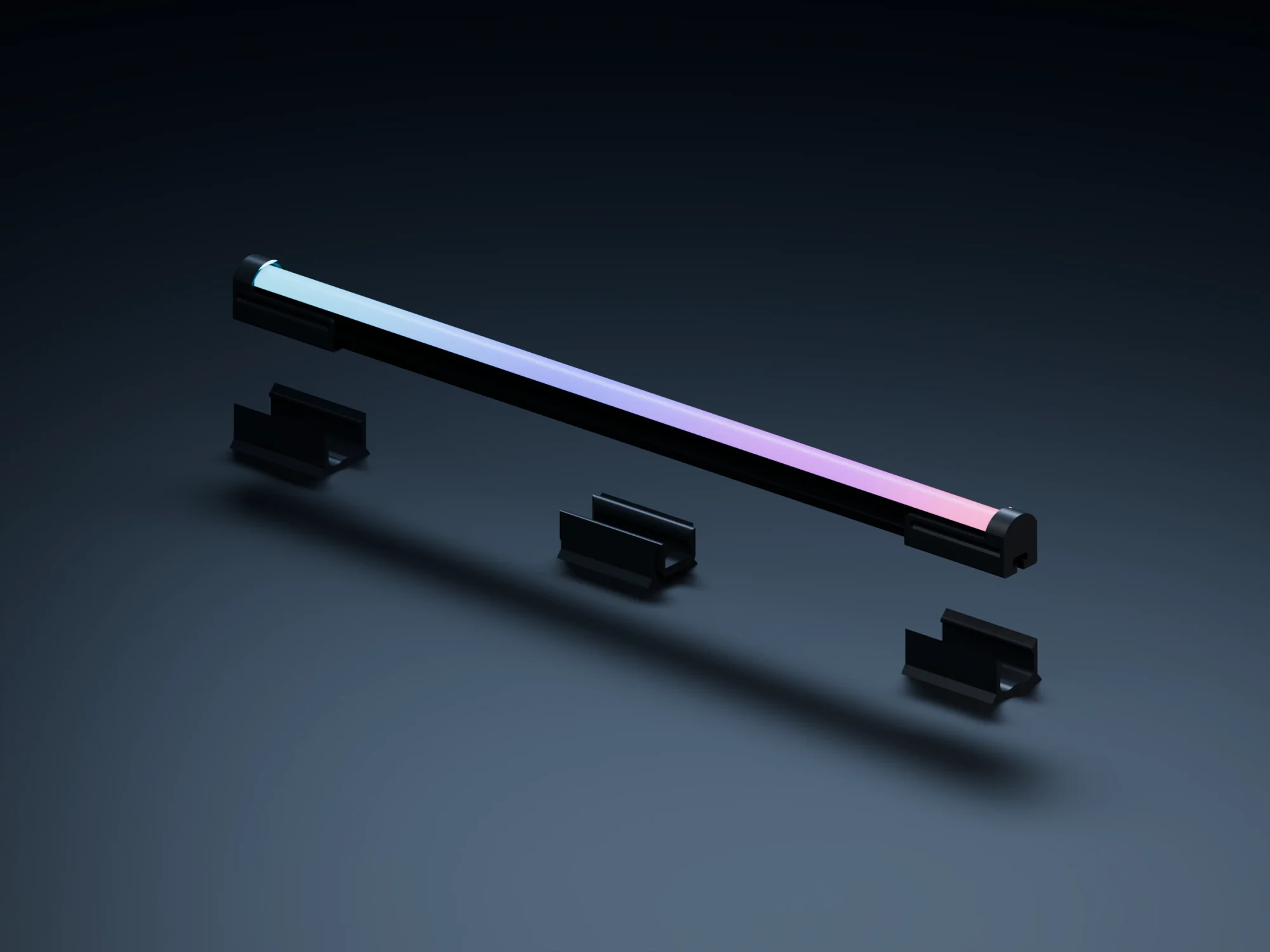
Original Loomx bar above its end-cap and mid-span snap baseplates
Your original Loomx snap mounting hardware.
  1. Mark your layout

    Match the shape and bar labels to your supplied plan. Check the ceiling or wall, cable routes and clearances before drilling. Use the mounting positions and fasteners specified for your surface.

  2. Fix the baseplates

    Each original surface baseplate has a central countersunk screw hole. Secure the plates with their snap openings facing the room. The end-cap mounts support the bar ends; the Snap-Mid-Mount supports the middle. Use every support shown in your kit’s mounting schedule.

  3. Snap the bars in

    Align the end caps and mid-mount with their baseplates, then press the assembled bar into the matching snap seats. Check that each seat is fully engaged before releasing the bar.

  4. Complete the pattern

    Match each triangle’s three bars to its shape label. Align them to the 60-degree layout marks, using each bar’s scheduled snap supports. Keep the planned gaps between neighboring triangle frames; each frame has its own set of bars.

Using cable suspension?
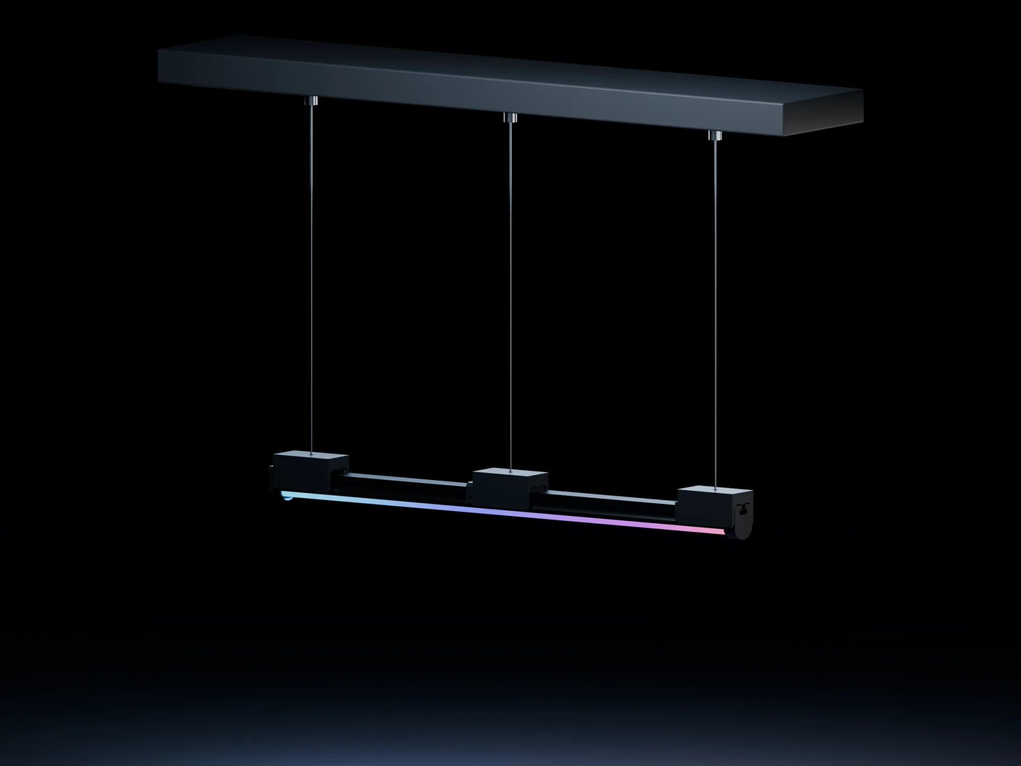
Original Loomx cable suspenders, steel cables and ceiling tensioners
Your original Loomx snap mounting hardware.
  1. Fix the ceiling anchors

    Use the specified anchor points and substrate-rated fixings. Match the anchor positions to the end-cap and mid-span suspension positions on the plan.

  2. Seat the cable hardware

    Run the steel cable through its supplied tensioner. The ball end seats in the cable suspender’s pocket; snapping the bar into the suspender locks the ball in place.

  3. Level and check

    Adjust the tensioners to the scheduled hanging height, then check every snap seat and cable attachment. Lighting leads must have slack and must not carry the bar’s weight.

Connect & start your kit
  1. Keep power unplugged

    Install the supplied computer, kit router or switch, controller nodes and matched power units in the locations marked on your plan. Keep vents clear and equipment accessible.

  2. Connect the network

    Connect the kit computer to the supplied switch. Run each node’s labeled Cat 6 cable back to the switch, matching the node number at both ends. Seat each Ethernet plug until its latch clicks and leave slack at the equipment. Keep the supplied network settings so the computer can find the nodes.

  3. Match each lighting lead

    Connect the labeled node output to the matching shape. Mate each female JST connector with its labeled male JST connector. Follow the light’s input/output arrows and connector labels; do not infer pin order or voltage from connector gender or wire color.

  4. Join bars within the shape

    Follow bar 1 → bar 2 and the remaining numbered links for that shape. Leave the final data output unconnected. A closed shape is a visual loop, not an electrical loop. Keep separate shapes and their power units isolated; any extra power feed must follow the supplied wiring schedule.

  5. Power up & test

    Check that all connectors are fully seated, then connect each matched power unit and turn on the kit computer. Open the preconfigured lighting software and run the labeled fixture test. Confirm every shape and color before playing a full scene. If a shape stays dark, unplug its power before checking its labels and connections.